I fixed my bumper switches and then, everything worked.
Monday, May 10, 2010
Sore Fingers
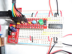
 I decided to move the circuit to a new breadboard. This one had tighter connections and made much better contact with the Ardweeny. After spending some time cutting a new set of wires, and forcing the connections into the breadboard, I had a second breadboard ready to go. (I wanted to keep the initial setup in case I had extra time to create a 2nd generation.)
Future Improvements
 I decided to move the circuit to a new breadboard. This one had tighter connections and made much better contact with the Ardweeny. After spending some time cutting a new set of wires, and forcing the connections into the breadboard, I had a second breadboard ready to go. (I wanted to keep the initial setup in case I had extra time to create a 2nd generation.)
Debugging
In addition to the LED problem above, the switches didn't seem to work and the forward direction was actually backwards. (I wired my motors opposite of the assumed wiring.)I spent some time researching (googling) microswitches and I found that I neded to change the way that I wired my switches. That's not surprising since I am new to this whole thing. I found Jearil's schematic on flickr that showed how he wired his bumper switches. Thanks Jearil!
Ideas for Robot Names
- Son of the one hour coaster bot
- Protocol error
- Ardweeny Nova - Spanish reference to No Va - as in No Go
- Red Hat Bot - reference to the Red Hat Linux Disks that I used
- Gitty Up Bot - reference to the guitar wire sensors
None of names really jump out at me. I guess I will just go with Protocol eError since I spent hours and hours and hours figuring out how to upload my code to the Ardweeny. I probably spent over 4 hours trying to get the code to upload.
Future Improvements
Add my ultrasonic range finder
- Smooth movement like JesterVineo
- Replace the servo motors with gear motors
- Replace L293 with Pololu motor controller
- Add more LEDs for visual appeal
- Create a second coasterbot and add RF communications between them
- Try to get two coasterbots to behave cooperatively

Protocol Error
When I tried to upload the new code to the Ardweeny I got this error:
avrdude: stk500_getsync(): not in sync: resp=0xf6
avrdude: stk500_disable(): protocol error, expect=0x14, resp=0x51
For some reason, I could no longer upload to the Ardweeny. Every time I tried to upload, I would get a "protocol error." Hmmm... that might be a good name for my coasterbot. I have a list of names that I considered later.
The error message also included a link to this Troubleshooting Guide. I read through the troubleshooting guide and verified that I was doing things correctly. One suggestion was to remove the Ardweeny from the circuit.
I removed the Ardweeny and tried uploading to it separately. That did not work. I also purchased a second Ardweeny, so I tried to upload to that one too. I got the same result. Now I could not upload to either Ardweeny.
Next, I googled the error code and found a few more ideas:
After I uploaded the code, I noticed that only one LED would blink during the start up. That didn't make sense. I checked the connections between the Ardweeny and the breadboard and realized that the Ardweeny was having problems staying seated in the breadboard. In fact, I could push down on the Ardweeny and it would still not seat completely.
When I tried to upload the new code to the Ardweeny I got this error:
avrdude: stk500_getsync(): not in sync: resp=0xf6
avrdude: stk500_disable(): protocol error, expect=0x14, resp=0x51
For some reason, I could no longer upload to the Ardweeny. Every time I tried to upload, I would get a "protocol error." Hmmm... that might be a good name for my coasterbot. I have a list of names that I considered later.
The error message also included a link to this Troubleshooting Guide. I read through the troubleshooting guide and verified that I was doing things correctly. One suggestion was to remove the Ardweeny from the circuit.
I removed the Ardweeny and tried uploading to it separately. That did not work. I also purchased a second Ardweeny, so I tried to upload to that one too. I got the same result. Now I could not upload to either Ardweeny.
Next, I googled the error code and found a few more ideas:
- Change the "RTS" option in the Advanced settings
- Hold the reset button on the Ardweeny while uploading and release it when the compile phase completes
- Try uploading the code from a different computer
After I uploaded the code, I noticed that only one LED would blink during the start up. That didn't make sense. I checked the connections between the Ardweeny and the breadboard and realized that the Ardweeny was having problems staying seated in the breadboard. In fact, I could push down on the Ardweeny and it would still not seat completely.
Adding Sensors
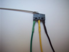
The contest requires some sensors. I have an ultrasonic range finder but, since this is my first robot, I thought I should stick with a couple of simple bumper switches like I saw in Absolute Beginner's Guide to Building Robots.
 Creating the bumper switches turned out to be more difficult than I anticipated. I soldered leads to each of the pins on the microswitch and added heat shrink tubing to protect the connections. Then I soldered about 5 inches of guitar wire to each switch to create an antenna-like bumper switch. I used double-stick tape to mount the switches on the front of the robot.
I should stop here to send out a big THANK YOU! I did not even know how to solder a couple of months ago. Then, I attended one of Mitch Altman's "Soldering Workshops" at the Haker Dojo in Mountain View. Since that workshop I've soldered a number of kits including the power supply and Ardweeny for this project.
Software Changes
Changing the software seemed like it would be fairly straightforward. I planned to start with the code from the one hour coasterbot and modify it to add the bumper switch sensors. I also added some leds to the robot to indicate when the bumper switch was activated - to help if I needed to debug. If I had more time, I could even adjust the placement of the leds to make them look more like eyes..
In the setup function, the pins on the ardweeny are initialized as inputs or outputs. I also made the leds blink back and forth and had the robot dance (spin) clockwise and counter clockwise.
In the loop section, I check the status of the bumper switches and depending on whether one is activated or both, execute some obsticle avoidance code. I also briefly turn on the left or right led based on which bumper switch is active (or both). After avoiding the obsticle and turning in a new direction, the robot will start moving forward again.
Here is the code -
/*
   Original Code to make the one hour robot dance!  Originally, this just turns the motors on and off,
   causing the robot to spin in circles. The code was modified to read some bumper switches that will
   detect obsticles, move away from the obsticle, and go in a new direction.

   Jeff> Added two bumper switches to the front of the coasterbot.
   Jeff> Added two Leds to indicate when switches are activated.
   Jeff> Added obsticle avoidance logic to backup, spin left, spin right.
 */

// These constants define which pins on the Ardweeny are connected to the pins on
// the motor controller, bumper switches and leds.

const unsigned char leftMotorA = 7;
const unsigned char leftMotorB = 8;

const unsigned char rightMotorA = 9;
const unsigned char rightMotorB = 10;

int leftSwitch = 6;
int rightSwitch = 11;

int leftLed = 4;
int rightLed = 12;

int readingLeftSwitch = LOW;     // the current reading from the left input pin
int readingRightSwitch= LOW;     // the current reading from the right input pin

// This function is run first when the microcontroller is turned on
void setup() {
  // Initialize the pins used to talk to the motors
  pinMode(leftMotorA, OUTPUT);
  pinMode(leftMotorB, OUTPUT);
  pinMode(rightMotorA, OUTPUT);
  pinMode(rightMotorB, OUTPUT);

  // Initialize the pins used to connect to the switches
  pinMode(leftSwitch, INPUT);
  pinMode(rightSwitch, INPUT);

  // Initialize the Leds used to display the switch status
  // This will help with debugging and will make it look cooler
  pinMode(leftLed, OUTPUT);
  pinMode(rightLed, OUTPUT);

  // Writing LOW to a motor pin instructs the L293D to connect its output to ground.
  digitalWrite(leftMotorA, LOW);
  digitalWrite(leftMotorB, LOW);
  digitalWrite(rightMotorA, LOW);
  digitalWrite(rightMotorB, LOW);

  // Make the 'eyes' blink back and forth on start up.
  digitalWrite(leftLed, HIGH);
  delay(1000);
  digitalWrite(leftLed, LOW);
  digitalWrite(rightLed, HIGH);
  delay(1000);
  digitalWrite(rightLed, LOW);
  digitalWrite(leftLed, HIGH);
  delay(1000);
  digitalWrite(leftLed, LOW);
  digitalWrite(rightLed, HIGH);
  delay(1000);
  digitalWrite(rightLed, LOW);

  // Then, make the wheels move back and forth
  // Point them in opposite directions, so the robot spins clockwise
  digitalWrite(leftMotorA, LOW);
  digitalWrite(leftMotorB, HIGH);
  digitalWrite(rightMotorA, HIGH);
  digitalWrite(rightMotorB, LOW);
  delay(1000); // Wait 1 second

  // Point them in opposite directions, so the robot spins counter clockwise
  digitalWrite(leftMotorA, HIGH);
  digitalWrite(leftMotorB, LOW);
  digitalWrite(rightMotorA, LOW);
  digitalWrite(rightMotorB, HIGH);
  delay(1000); // Wait 1 second

  // Time to start moving.....Turn both motors on, in the 'forward' direction
  digitalWrite(leftMotorA, LOW);
  digitalWrite(leftMotorB, HIGH);
  digitalWrite(rightMotorA, LOW);
  digitalWrite(rightMotorB, HIGH);
  delay(1000);  // Wait 1 second
}

// This function gets called repeatedly while the microcontroller is on.
void loop() {

   // check the value of the bumper switches
   readingLeftSwitch = digitalRead(leftSwitch);
   readingRightSwitch = digitalRead(rightSwitch);

  if (readingLeftSwitch == HIGH) {
    digitalWrite (leftLed, HIGH);
    if (readingRightSwitch == HIGH) {
      digitalWrite(rightLed, HIGH);
      // both sensors touching, need to backup

      // Turn both motors on, in the 'backward' direction
     digitalWrite(leftMotorA, HIGH);
     digitalWrite(leftMotorB, LOW);
     digitalWrite(rightMotorA, HIGH);
     digitalWrite(rightMotorB, LOW);
     delay(1000); // Wait 1 second

     // Turn off Leds
     digitalWrite(leftLed, LOW);
     digitalWrite(rightLed, LOW);

     // Point them in opposite directions, so the robot spins clockwise
     digitalWrite(leftMotorA, LOW);
     digitalWrite(leftMotorB, HIGH);
     digitalWrite(rightMotorA, HIGH);
     digitalWrite(rightMotorB, LOW);
     delay(1000); //Wait 1 second

     // Now go forward again - done at the end of the if statement

    } else { // backup to the right
     // Point them in opposite directions, so the robot spins counter clockwise
     digitalWrite(leftMotorA, HIGH);
     digitalWrite(leftMotorB, LOW);
     digitalWrite(rightMotorA, LOW);
     digitalWrite(rightMotorB, HIGH);
     delay(1000); //Wait 1 second

     // Turn off Led
     digitalWrite(leftLed, LOW);

     // Now go forward again - done at the end of the if statement

    }
  } else { // readingLeftSwitch is Low
     if (readingRightSwitch == HIGH) {
     digitalWrite(rightLed, HIGH);

     // Point them in opposite directions, so the robot spins clockwise
     digitalWrite(leftMotorA, LOW);
     digitalWrite(leftMotorB, HIGH);
     digitalWrite(rightMotorA, HIGH);
     digitalWrite(rightMotorB, LOW);

     // Wait 1 second
     delay(1000);

     // Turn off Led
     digitalWrite(rightLed, LOW);

     // Now go forward again - done at the end of the if statement
     }
  }
  // Continue moving forward  .....Turn both motors on, in the 'forward' direction
  digitalWrite(leftMotorA, LOW);
  digitalWrite(leftMotorB, HIGH);
  digitalWrite(rightMotorA, LOW);
  digitalWrite(rightMotorB, HIGH);
  delay(1000);   // Move forward one second and loop again
}
Starting the Coasterbot
To be honest, I was not sure how I would start my robot project. I had recently purchased a copy of Absolute Beginner's Guide to Building Robots
and Chapter 9 described a CD ROM based robot built using an OOPIC microcontroller. I thought that I might follow the instructions in the book and replace the OOPIC with an Arduino. This was going to be my first robot after all. I didn't have enough experience to build something from scratch.
Then, I saw the posting on the Make: Blog - Make: Robot Build: The one hour CoasterBot. Wow! Here was a complete set of directions that included using an Arduino. The only thing that I would need to add is a sensor.
 Assembly of the Coasterbot
I assembled the parts following the instructions. My Ardweeny was having problems staying in the breadboard. (This ended up causing a big delay later on.) I'll admit that it took me a lot longer than 1 hour to put everything together. I'm not an expert at cutting wires and making breadboard connections. It takes practice to get fast at cutting wires, getting them the right length, and inserting the wires into the breadboard. My fingertips are still a bit sore from jamming the wires into new, tight fitting, breadboard connections.
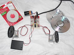
I continued following the instructions and used double stick foam tape to connect the servos, battery pack, breadboard, and 9V battery. Double stick tape makes it very easy to put everything together. I spent a little time getting everything aligned. The most difficult part was getting the alignment correct for the battery pack sitting between the servos. I drew some lines on the CD to help with the alignment.
The CD "sandwich" was a little off since the 9V battery was sitting with the wider side up. I added a plastic ball caster that was not part of the original plans. The caster would help the robot move more smoothly.
Initial Programming
Then, I got out my FTDI programming cable and loaded the provided code. I uploaded the code to the Ardweeny without any problems. The first time I powered it up, it worked! The robot did a little dance. It was very impressive. My kids came into the room to see the robot do its dance.
Now it's time to modify this "one hour coasterbot," add some sensors and some obsticle avoidance code.
To be honest, I was not sure how I would start my robot project. I had recently purchased a copy of Absolute Beginner's Guide to Building Robots
and Chapter 9 described a CD ROM based robot built using an OOPIC microcontroller. I thought that I might follow the instructions in the book and replace the OOPIC with an Arduino. This was going to be my first robot after all. I didn't have enough experience to build something from scratch.
Then, I saw the posting on the Make: Blog - Make: Robot Build: The one hour CoasterBot. Wow! Here was a complete set of directions that included using an Arduino. The only thing that I would need to add is a sensor.
I assembled the parts following the instructions. My Ardweeny was having problems staying in the breadboard. (This ended up causing a big delay later on.) I'll admit that it took me a lot longer than 1 hour to put everything together. I'm not an expert at cutting wires and making breadboard connections. It takes practice to get fast at cutting wires, getting them the right length, and inserting the wires into the breadboard. My fingertips are still a bit sore from jamming the wires into new, tight fitting, breadboard connections.
I continued following the instructions and used double stick foam tape to connect the servos, battery pack, breadboard, and 9V battery. Double stick tape makes it very easy to put everything together. I spent a little time getting everything aligned. The most difficult part was getting the alignment correct for the battery pack sitting between the servos. I drew some lines on the CD to help with the alignment.
The CD "sandwich" was a little off since the 9V battery was sitting with the wider side up. I added a plastic ball caster that was not part of the original plans. The caster would help the robot move more smoothly.
Initial Programming
Then, I got out my FTDI programming cable and loaded the provided code. I uploaded the code to the Ardweeny without any problems. The first time I powered it up, it worked! The robot did a little dance. It was very impressive. My kids came into the room to see the robot do its dance.
Now it's time to modify this "one hour coasterbot," add some sensors and some obsticle avoidance code.
Background
I'm rediscovering my engineering roots. After working for a number of years in Silicon Valley, my work have evolved to a point where I'm no longer writing code or creating things. Don't get me wrong, I'm not complaining. I think we all need to grow and do new things and experience new challenges. For me, being an engineer provides an opportunity to learn new things and challenge yourself with each new project.
With that in mind, I decided to enter The Make: Robot Build.
I entered the contest and started accumulating parts. I decided not to purchase the Jameco Robot Build Starter Kit since I already owned a bunch of parts. I did need to add to my supply so, I purchassed Wheel & Tire Set, hex spacers, breadboards, L293D Quadruple Half-H Driver from Jameco. I should say that I'm a huge fan of Jameco. They are here in Silicon Valley and if I need something quickly, it's only a 15 minute drive up highway 101 to their location.
Ahh, the best laid plans. Things at work got busy. I went on a trip to Asia and I needed to the taxes and pretty soon I was down to the last week before the deadline for submission. Thankfully, the deadline was extended to Monday, May 10th, 2010 so that I could use the weekend to finish up.
Sunday, May 09, 2010
This is a test of posting code using SyntaxHighlighter
Test with Processing Code for Blink
Test with Processing Code for Blink
/*
  Blink
 Turns on an LED on for one second, then off for one second, repeatedly.
 The circuit:
 * LED connected from digital pin 13 to ground.
 * Note: On most Arduino boards, there is already an LED on the board
 connected to pin 13, so you don't need any extra components for this example.
 Created 1 June 2005
 By David Cuartielles
 http://arduino.cc/en/Tutorial/Blink
 based on an orginal by H. Barragan for the Wiring i/o board
 */

int ledPin =  13;    // LED connected to digital pin 13
// The setup() method runs once, when the sketch starts
void setup()   {
  // initialize the digital pin as an output:
  pinMode(ledPin, OUTPUT);
}

// the loop() method runs over and over again,
// as long as the Arduino has power

void loop()
{
  digitalWrite(ledPin, HIGH);   // set the LED on
  delay(1000);                  // wait for a second
  digitalWrite(ledPin, LOW);    // set the LED off
  delay(1000);                  // wait for a second
}
